Projects: Data-Link Layer#
In Theory: Data-Link Layer, we covered the theory behind the data-link layer, including Ethernet and how frames are used to move data between computers. Now you’ll get your hands dirty with several projects to learn how the data-link layer works in the real world. In these projects we’ll capture Ethernet and Bluetooth packets, work with RF tags, push our network to see how much data it can manage, learn to read sensor data, and even hook into your car’s network to read diagnostic information.
We’ll start the chapter off learning how to capture and analyze data frames using a tool called Wireshark. Next, we’ll learn to set and use MAC addresses work to specify what computer our data is for. In another project, you will learn to construct your own Ethernet packets to send and receive. We will learn to test how fast our data line can send/receive data by using the iperf3 tool. Sending data isn’t just limited to Ethernet, we’ll also try receiving data via Bluetooth, read and write RF tags with NFC, read sensors and control electronics with I2C, and even get data from your car over ODB-II.
Project: Capture and Investigate Packets with Wireshark#
Wireshark is a packet-sniffer program that lets you see what is going on with the network and inspect each individual frame that’s transmitted. This tool is useful for debugging connection errors, understanding why a program is slow, reverse-engineering protocols, and finding what software is sending data and not telling you about it.
Warning
Don’t get fired or expelled! Some people consider Wireshark to be an “offensive weapon” in the area of network security, and they won’t want it hooked up to their network. Depending on policy, if you use this tool at your workplace or school, it could lead to disciplinary action. Keep packet-sniffing to networks you own or have permission to use for that purpose.
You can run this tool on most types of computers, although there are some limitations with Windows. I recommend using a Raspberry Pi or two, as they make it easy and cheap to set up a separate network to experiment with. The tutorial below shows how to set up Wireshark with the Raspberry Pi. For macOS and Windows, go to http://www.wireshark.org and download the installer.
Installing Wireshark on Linux#
Before installing Wireshark on your Raspberry Pi, make sure everything you have installed is up to date to avoid incompatible versions of software. First, get an updated list of software you can install with the command:
sudo apt-get update
Enter the following to upgrade your currently installed software to the latest version:
sudo apt-get upgrade
To install Wireshark, enter:
sudo apt-get install wireshark
The install command dumps a lot of information to the screen about what it will install:
pi@raspberrypi:~ $ sudo apt-get install wireshark
Reading package lists... Done
Building dependency tree
Reading state information... Done
The following additional packages will be installed:
  libc-ares2 libmaxminddb0 libnl-route-3-200 libpcap0.8 ...
Suggested packages:
  mmdb-bin qt5-qmltooling-plugins snmp-mibs-downloader wireshark-doc
The following NEW packages will be installed:
  libc-ares2 libmaxminddb0 libnl-route-3-200 libpcap0.8 ...
0 upgraded, 21 newly installed, 0 to remove and 41 not upgraded.
Need to get 15.4 MB/18.3 MB of archives.
After this operation, 85.0 MB of additional disk space will be used.
Do you want to continue? [Y/n] y
The Wireshark program depends on other libraries to run. The install command will let you know what other packages it will install and how much disk space it will take. The last line asks if you really want to install Wireshark. Enter y to confirm. If you get a warning that begins with Dumpcap can be installed, select No.
Wireshark requires low-level access to your networking hardware to capture raw data packets. The default user account does not have this permission. We need to give it elevated privileges, which we can get by putting sudo in front of the command to run Wireshark:
sudo wireshark
This will start the Wireshark GUI and you’ll be ready to start capturing packets.
Capturing Packets#
Once you’ve installed Wireshark, open it to begin listening in on a network connection to capture packets. Wireshark will display a welcome screen similar to Fig. 51, which lists all of the network adapters you can listen to.

Fig. 51 Opening screen for Wireshark#
Wireshark also displays a small graph that shows how much network traffic is passing through each interface. Double-click the interface from which you want to capture networking data. In Fig. 51, I’ve selected the wireless Wi-Fi interface.
Wireshark may also show an interface labeled Any. In my experience, information gets stripped off from packets captured with Any. Instead, use the Wi-Fi to capture wireless packets or Local Area Connection for wired connections.
Once you start capturing, Wireshark will collect data until you click the stop button. It’s best to capture for a short period of time (five or so seconds), as capturing for longer will store hundreds or thousands of packets, making it difficult to find the ones you’re interested in. You can filter packets with a Wireshark filter language, though this is out of the scope of this book.
To test Wireshark’s deciphering abilities, find an unencrypted web page that starts with starts with http and not https, such as http://programarcadegames.com. Start a capture in Wireshark, then immediately load the web page in a browser and stop the capture. See if you can use Wireshark to find the frames associated with the web page download.
For example, take a look at Fig. 52, in which I’ve used Wireshark to find part of a web page.

Fig. 52 Layer 2 data frame shown in Wireshark#
The top third of the window is a list of every data frame, numbered in the order it was received. In this example, I selected frame 35, received 2.19 seconds after I started capturing.
The middle section of Fig. 52 allows the user to select what part of the data frame to look at and helps decode it. Typically, you’ll use Ethernet II for Layer 2. After selecting Ethernet II, Wireshark will highlight the Layer 2 parts of the data and decode each field. (Wireshark also has lines for Layer 3 and Layer 4, which I’ll describe in later chapters.)
The bottom section lists the data in the packet. It gives each byte as a two-digit hexadecimal number and attempts to decode it to text on the far right. You can see the HTML for the web page there.
For now, concentrate on finding and identifying the information in the Layer 2 Ethernet II section, specifically the MAC source and destination addresses. In this section, you can see how often your computer is receiving data; what data it is sending out; where that data is going; and the content of that data.
Project: Finding the MAC Address#
Computers often have more than one network adapter. Raspberry Pi computers, for example, typically have three: one for a wired network connection, one for wireless network connections, and a third if the computer needs to create a connection back to itself. These adapters are officially known as network interface cards (NICs). Often, network adapters are built in, rather than separate cards.
Each network adapter has a default, distinctive Layer 2 MAC address set by the manufacturer. Remember, this MAC address is an entirely different address from the IP address. The MAC address gets us from one node directly to another (Chapter 4). The IP address is used for routing across multiple hops. You’ll learn more about IP addresses in Chapter 6, which discusses Layer 3.
If you’re using macOS or Linux, open a terminal window and enter
ifconfig to find details on your network adapters:
 1pi@raspberrypi:~ $ ifconfig
 2eth0: flags=4099<UP,BROADCAST,MULTICAST>  mtu 1500
 3        ether b8:27:eb:28:42:66  txqueuelen 1000  (Ethernet)
 4        RX packets 0  bytes 0 (0.0 B)
 5        RX errors 0  dropped 0  overruns 0  frame 0
 6        TX packets 0  bytes 0 (0.0 B)
 7        TX errors 0  dropped 0 overruns 0  carrier 0  collisions 0
 8
 9lo: flags=73<UP,LOOPBACK,RUNNING>  mtu 65536
10        inet 127.0.0.1  netmask 255.0.0.0
11        inet6 ::1  prefixlen 128  scopeid 0x10<host>
12        loop  txqueuelen 1000  (Local Loopback)
13        RX packets 29  bytes 4572 (4.4 KiB)
14        RX errors 0  dropped 0  overruns 0  frame 0
15        TX packets 29  bytes 4572 (4.4 KiB)
16        TX errors 0  dropped 0 overruns 0  carrier 0  collisions 0
17
18wlan0: flags=4163<UP,BROADCAST,RUNNING,MULTICAST>  mtu 1500
19        inet 192.168.1.107  netmask 255.255.255.0  broadcast 192.168.1.255
20        inet6 fe80::d1ea:5ebd:506e:5ed3  prefixlen 64  scopeid 0x20<link>
21        ether b8:27:eb:7d:17:33  txqueuelen 1000  (Ethernet)
22        RX packets 35656  bytes 6337537 (6.0 MiB)
23        RX errors 0  dropped 0  overruns 0  frame 0
24        TX packets 1014  bytes 101325 (98.9 KiB)
25        TX errors 0  dropped 0 overruns 0  carrier 0  collisions 0
The MAC address of the wired connection eth0 is at b8:27:eb:28:42:66 (line 3),
and the MAC address for the wireless wlan0 connection is
b8:27:eb:7d:17:33 (line 21). Wired connections start with eth, which is short
for Ethernet. For Linux, wireless connections start with wlan, short for
Wireless Local Area Network. The macOS wireless adapters start with en.
The lo connector is a virtual adapter called the loopback connector. It allows a computer to create a network connection with itself, which can be useful in various scenarios; for example, if you have to run a web server and connect to it with a web browser on the same computer.
On Windows, use the ipconfig command to find network information. By
default, ipconfig doesn’t show all the information, so you need to add
the /all option:
 1C:\Users\craven>ipconfig /all
 2
 3Windows IP Configuration
 4
 5   Host Name . . . . . . . . . . . . : livingroom-pc
 6   Primary Dns Suffix  . . . . . . . :
 7   Node Type . . . . . . . . . . . . : Hybrid
 8   IP Routing Enabled. . . . . . . . : No
 9   WINS Proxy Enabled. . . . . . . . : No
10   DNS Suffix Search List. . . . . . : domain.actdsltmp
11
12Ethernet adapter Ethernet:
13
14   Connection-specific DNS Suffix  . : domain.actdsltmp
15   Description . . . . . . . . . . . : Realtek PCIe GBE Family Controller
16   Physical Address. . . . . . . . . : 1C-6F-65-3E-6B-82
17   DHCP Enabled. . . . . . . . . . . : Yes
18   Autoconfiguration Enabled . . . . : Yes
19   Link-local IPv6 Address . . . . . : fe80::b551:7120:2f3b:78c2%4(Preferred)
20   IPv4 Address. . . . . . . . . . . : 192.168.0.4(Preferred)
21   Subnet Mask . . . . . . . . . . . : 255.255.255.0
22   Lease Obtained. . . . . . . . . . : Thursday, January 10, 2019 4:09:16 AM
23   Lease Expires . . . . . . . . . . : Friday, January 11, 2019 4:09:16 AM
24   Default Gateway . . . . . . . . . : 192.168.0.1
25   DHCP Server . . . . . . . . . . . : 192.168.0.1
26   DHCPv6 IAID . . . . . . . . . . . : 52195173
27   DHCPv6 Client DUID. . . . . . . . : 00-01-00-01-1A-BA-AF-CA-1C-6F-65-3E-6B-82
28   DNS Servers . . . . . . . . . . . : 192.168.0.1
29                                       205.171.3.25
30   NetBIOS over Tcpip. . . . . . . . : Enabled
Here you can see the MAC address is 1C-6F-65-3E-6B-82 (line 16). Much of the
other information listed is Layer 3 information, which we will cover in
Chapters 7 and 8.
Project: Change Your MAC Address#
The manufacturer sets your MAC address automatically. The local network uses it to identify each computer uniquely—but that individuality can be used to invade a person’s privacy. By tracking one’s MAC address, you can keep tabs on when a person’s phone is in range of a network, what kind of phone or computer they have, and more.
If a MAC address changes each time it connects to a network, the network can’t use that address to track a person across connections. MAC addresses also have built-in address ranges for each manufacturer, and changing the address keeps a person from using the address to find what kind of hardware you are using. You can even replace a network device and have the new device use the old MAC address; the network can’t tell the device was replaced.
Linux, Windows, and Mac computers include programs to customize a MAC address. However, there are rules for creating a valid MAC address. The first byte must have a value other than zero, and it cannot end in a binary zero. This means you should avoid starting your custom MAC address with an odd number or 00. Try 02, 04, 06, 08, and so on. Odd numbers are used for multi-cast addresses when the same data is broadcast to multiple computers.
On Windows#
To change the MAC address on Windows, open the Control Panel, search for View Network Connections, right-click your active network connection, and select Properties (Fig. 53).

Fig. 53 Opening network properties#
A list of different drivers that have hooks into your network connection appears. Click the Configure button (see Fig. 54).

Fig. 54 Network adapter properties#
Click the Advanced tab, select Network Address (Fig. 55), and click the radio button with an empty field next to it.
NOTE Depending on your computer’s networking hardware, this might be labeled differently. If there is no item available to change the network address, the method described here won’t work.
Type in your own six-byte address with no spaces, for example:
AABBCCDDEEFF.

Fig. 55 Changing the MAC address#
Click OK. Go back to the command prompt and type ipconfig /all
to test. If the MAC address didn’t change, make sure you started the
address with an even number, such as 02 or higher. Also try enabling and
disabling the interface, which can be done via the menu shown in
Fig. 53.
On macOS or Linux#
When you enter ifconfig on a Mac or Linux, the current network configuration information appears and lists all interfaces. To change the address we need to turn off the networking device by issuing a “down” command, adjusting the address, then turn it back on with an “up” command. To do this on Linux:
sudo ifconfig wlan0 down
sudo ifconfig wlan0 hw ether AA:04:05:06:07:08
sudo ifconfig wlan0 up
For macOS, the procedure is a bit different. Typically, en0 is the device name instead of wlan0, and you don’t need to add the hw (hardware) parameter. Here are the steps for macOS:
sudo ifconfig en0 down
sudo ifconfig en0 ether AA:04:05:06:07:08
sudo ifconfig en0 up
Note
You can do a lot with the ifconfig command; for example, to get
its manual, type man ifconfig at the command line or search
“man ifconfig”” on the internet.
Project: Sending Raw Ethernet Packets#
Let’s try making our own Layer 2 data frame. We’ll have one program send a frame, and one receive it.
This is easiest on a Linux computer like the Raspberry Pi since the development tools are built in. We’ll be doing this in the C language.
Sending Raw Packets#
The code to send a frame is available below:
  1/*
  2 *  This program is free software: you can redistribute it and/or modify
  3 *  it under the terms of the GNU General Public License as published by
  4 *  the Free Software Foundation, either version 3 of the License, or
  5 *  (at your option) any later version.
  6 *
  7 * Original version from Austin Martin:
  8 * https://gist.github.com/austinmarton/1922600
  9 *
 10 * Adapted by Paul Craven
 11 */
 12
 13#include <arpa/inet.h>
 14#include <linux/if_packet.h>
 15#include <stdio.h>
 16#include <string.h>
 17#include <stdlib.h>
 18#include <sys/ioctl.h>
 19#include <sys/socket.h>
 20#include <net/if.h>
 21#include <netinet/ether.h>
 22#include <unistd.h>
 23
 24/* ALERT: Replace the bytes below with the MAC address
 25   you are sending to.
 26   So if 'ifconfig' on the RECEIVER (not the sender) says:
 27   wlan0     Link encap:Ethernet  HWaddr b8:27:eb:44:08:62
 28   You'd replace the bytes below with:
 29   #define DEST_MAC0 0xB8
 30   #define DEST_MAC1 0x27
 31   #define DEST_MAC2 0xEB
 32   #define DEST_MAC3 0x44
 33   #define DEST_MAC4 0x08
 34   #define DEST_MAC5 0x62
 35*/
 36
 37#define DEST_MAC0    0xB8
 38#define DEST_MAC1    0x27
 39#define DEST_MAC2    0xEB
 40#define DEST_MAC3    0x44
 41#define DEST_MAC4    0x08
 42#define DEST_MAC5    0x62
 43
 44/* ALERT: Update the field below to specify what network
 45  adapter should we send data through. */
 46#define DEFAULT_IF  "wlan0"
 47
 48#define BUF_SIZ     1024
 49
 50int main(int argc, char *argv[])
 51{
 52    int sockfd;
 53    int i;
 54    struct ifreq if_idx;
 55    struct ifreq if_mac;
 56    int tx_len;
 57    char sendbuf[BUF_SIZ];
 58    struct sockaddr_ll socket_address;
 59    char ifName[IFNAMSIZ];
 60
 61    /* Get interface name */
 62    if (argc > 1)
 63        strcpy(ifName, argv[1]);
 64    else
 65        strcpy(ifName, DEFAULT_IF);
 66
 67    /* Open RAW socket to send on */
 68    if ((sockfd = socket(AF_PACKET, SOCK_RAW, IPPROTO_RAW)) == -1) {
 69        perror("socket");
 70    }
 71
 72    /* Get the index of the interface to send on */
 73    memset(&if_idx, 0, sizeof(struct ifreq));
 74    strncpy(if_idx.ifr_name, ifName, IFNAMSIZ-1);
 75    if (ioctl(sockfd, SIOCGIFINDEX, &if_idx) < 0)
 76        perror("SIOCGIFINDEX");
 77
 78    /* Get the MAC address of the interface to send on */
 79    memset(&if_mac, 0, sizeof(struct ifreq));
 80    strncpy(if_mac.ifr_name, ifName, IFNAMSIZ-1);
 81    if (ioctl(sockfd, SIOCGIFHWADDR, &if_mac) < 0)
 82        perror("SIOCGIFHWADDR");
 83
 84    // Loop forever
 85    while(1) {
 86
 87
 88        /* Buffer of BUF_SIZ bytes we'll construct our frame in.
 89           First, clear it all to zero. */
 90        memset(sendbuf, 0, BUF_SIZ);
 91        tx_len = 0;
 92
 93        /* Construct the Ethernet header */
 94
 95        /* Ethernet header */
 96        /* Destination address */
 97        sendbuf[tx_len++] = DEST_MAC0;
 98        sendbuf[tx_len++] = DEST_MAC1;
 99        sendbuf[tx_len++] = DEST_MAC2;
100        sendbuf[tx_len++] = DEST_MAC3;
101        sendbuf[tx_len++] = DEST_MAC4;
102        sendbuf[tx_len++] = DEST_MAC5;
103
104        /* Create the source */
105        sendbuf[tx_len++] = ((uint8_t *)&if_mac.ifr_hwaddr.sa_data)[0];
106        sendbuf[tx_len++] = ((uint8_t *)&if_mac.ifr_hwaddr.sa_data)[1];
107        sendbuf[tx_len++] = ((uint8_t *)&if_mac.ifr_hwaddr.sa_data)[2];
108        sendbuf[tx_len++] = ((uint8_t *)&if_mac.ifr_hwaddr.sa_data)[3];
109        sendbuf[tx_len++] = ((uint8_t *)&if_mac.ifr_hwaddr.sa_data)[4];
110        sendbuf[tx_len++] = ((uint8_t *)&if_mac.ifr_hwaddr.sa_data)[5];
111
112        /* Ethertype field */
113        sendbuf[tx_len++] = 0x08;
114        sendbuf[tx_len++] = 0x00;
115
116        /*
117        UPDATE: Packet data
118        This is the 'payload'. Replace this with your real data.
119        Because you'll probably have more interesting things to send
120        than the hex 0xDEAD 0xBEEF
121        */
122        sendbuf[tx_len++] = 0xde;
123        sendbuf[tx_len++] = 0xad;
124        sendbuf[tx_len++] = 0xbe;
125        sendbuf[tx_len++] = 0xef;
126
127        /* Index of the network device */
128        socket_address.sll_ifindex = if_idx.ifr_ifindex;
129        /* Address length*/
130        socket_address.sll_halen = ETH_ALEN;
131        /* Destination MAC */
132        socket_address.sll_addr[0] = DEST_MAC0;
133        socket_address.sll_addr[1] = DEST_MAC1;
134        socket_address.sll_addr[2] = DEST_MAC2;
135        socket_address.sll_addr[3] = DEST_MAC3;
136        socket_address.sll_addr[4] = DEST_MAC4;
137        socket_address.sll_addr[5] = DEST_MAC5;
138
139        /* Send packet */
140        if (sendto(sockfd, sendbuf, tx_len, 0, (struct sockaddr*)&socket_address, sizeof(struct sockaddr_ll)) < 0)
141            printf("Send failed\n");
142        else {
143            printf("Sent :");
144            for (i=0; i < tx_len; i++)
145                printf("%02x:", sendbuf[i]);
146            printf("\n");
147        }
148        /* Wait specified number of microseconds
149           1,000,000 microseconds = 1 second
150           */
151        usleep(1000000);
152    }
153    return 0;
154}
This code can send raw Ethernet packets, and it allows you to set all
the bytes on what is sent out as a message. To run this code, simply
copy it and save it in a file on your computer. Note that C files should
end in .c, so name this file send_raw_ethernet.c. Spend some time
reading through the code and the comments to learn more about how it
works. You can adjust the program to specify the networking interface it
will send the message on. You can also update your destination MAC
address and the data to be sent.
Next, you have to translate the human readable C code to machine code
the computer can understand. This is done with a program called a
compiler. Enter gcc on the Raspberry Pi’s command line to use the
GNU C Compiler (gcc). Give it the name of your input C language file,
and the name of the program you want it to output, such as send.
gcc send_raw_ethernet.c -o send
Check the output to make sure you do not have any errors, which could be caused by not typing in the program correctly. If there are no errors, the compiled program will be stored in the send file. The compiler will not print anything if successful.
Running a C Program#
Normally, you can run a program by simply entering its name, such as send in this case. However to access the networking hardware directly like this program is, you need to request admin privileges by using the sudo command. Anytime you run a program with admin privileges, you also have to specify the directory it’s in if not a system directory. We can specify the current directory with a period. Therefore, to request admin privileges, specify the current directory, and run the program our command is:
sudo ./send
Running this command should send our own custom Ethernet data frame over the network. To ensure this worked, use Wireshark to see the data frame being transmitted by our program. Inspect the data that was sent, and see how it compares with the data that the C program sent out. Update your program to change the data, recompile it, and watch for the updated data being sent.
Receiving Raw Packets#
To receive the packets we sent, look at receive_raw_ethernet.c: C program to receive a raw ethernet packet. You’ll need to update this program with your computer’s MAC address and the name of the adapter you want it to use.
  1/*
  2 *  This program is free software: you can redistribute it and/or modify
  3 *  it under the terms of the GNU General Public License as published by
  4 *  the Free Software Foundation, either version 3 of the License, or
  5 *  (at your option) any later version.
  6 *
  7 * Original version from Austin Martin:
  8 * https://gist.github.com/austinmarton/2862515
  9 *
 10 * Adapted by Paul Craven
 11 */
 12
 13#include <arpa/inet.h>
 14#include <linux/if_packet.h>
 15#include <linux/ip.h>
 16#include <linux/udp.h>
 17#include <stdio.h>
 18#include <string.h>
 19#include <stdlib.h>
 20#include <sys/ioctl.h>
 21#include <sys/socket.h>
 22#include <net/if.h>
 23#include <netinet/ether.h>
 24
 25/* Replace this with this computer's MAC address
 26   In this case, the MAC address is b8:27:eb:44:08:62.
 27   You need to update this.
 28*/
 29#define DEST_MAC0 0xB8
 30#define DEST_MAC1 0x27
 31#define DEST_MAC2 0xEB
 32#define DEST_MAC3 0x44
 33#define DEST_MAC4 0x08
 34#define DEST_MAC5 0x62
 35
 36#define ETHER_TYPE  0x0800
 37
 38/* Change this to your interface name.
 39   Such as "wlan0" or "eth0".
 40   This program seems to ignore this parameter, and
 41   listens to everything.
 42   */
 43
 44#define DEFAULT_IF  "eth0"
 45#define BUF_SIZ     1024
 46
 47int main(int argc, char *argv[])
 48{
 49    int sockfd, i;
 50    int sockopt;
 51    ssize_t numbytes;
 52    struct ifreq ifopts;    /* set promiscuous mode */
 53    uint8_t buf[BUF_SIZ];
 54    char ifName[IFNAMSIZ];
 55
 56    /* --- Get ready to listen --- */
 57
 58    /* Copy the interface name to a character buffer */
 59    strcpy(ifName, DEFAULT_IF);
 60
 61    /* Open PF_PACKET socket, listening for EtherType ETHER_TYPE */
 62    if ((sockfd = socket(PF_PACKET, SOCK_RAW, htons(ETHER_TYPE))) == -1) {
 63        perror("listener: socket");
 64        return -1;
 65    }
 66
 67    /* Set interface to promiscuous mode - do we need to do this every time? */
 68    strncpy(ifopts.ifr_name, ifName, IFNAMSIZ-1);
 69    ioctl(sockfd, SIOCGIFFLAGS, &ifopts);
 70    ifopts.ifr_flags |= IFF_PROMISC;
 71    ioctl(sockfd, SIOCSIFFLAGS, &ifopts);
 72
 73    /* Allow the socket to be reused - in case connection is closed prematurely */
 74    if (setsockopt(sockfd, SOL_SOCKET, SO_REUSEADDR, &sockopt, sizeof sockopt) == -1) {
 75        perror("setsockopt");
 76        close(sockfd);
 77        exit(EXIT_FAILURE);
 78    }
 79    /* Bind to device */
 80    if (setsockopt(sockfd, SOL_SOCKET, SO_BINDTODEVICE, ifName, IFNAMSIZ-1) == -1)  {
 81        perror("SO_BINDTODEVICE");
 82        close(sockfd);
 83        exit(EXIT_FAILURE);
 84    }
 85
 86    /* --- Main loop to listen, and print a packet --- */
 87
 88    // Loop forever
 89    while(1) {
 90
 91        /* Receive the data */
 92
 93        //printf("Listener: Waiting to receive...\n");
 94        numbytes = recvfrom(sockfd, buf, BUF_SIZ, 0, NULL, NULL);
 95        //printf("Listener: got packet %lu bytes\n", numbytes);
 96
 97        /* Check the packet is for me
 98           by looking at the destination address. */
 99        if (buf[0] == DEST_MAC0 &&
100            buf[1] == DEST_MAC1 &&
101            buf[2] == DEST_MAC2 &&
102            buf[3] == DEST_MAC3 &&
103            buf[4] == DEST_MAC4 &&
104            buf[5] == DEST_MAC5) {
105
106            // printf("Correct destination MAC address\n");
107
108            if(buf[14] == 0x45) {
109                /* This is likely just an SSH packet from a
110                   remove SSH terminal. Let's ignore those
111                   and not do anything here.
112                */
113
114            } else {
115                /* We've got data!
116                   Print the packet */
117                printf("Data:");
118                for (i=0; i<numbytes; i++)
119                    printf("%02x:", buf[i]);
120                printf("\n");
121            }
122
123        } else {
124            /* Ok, this data was not intended for us.
125                   Which means we plugged in the wrong MAC
126               Or it was sent to ff:ff:ff:ff:ff:ff which is
127                   broadcast for 'everyone'
128
129            printf("Wrong destination MAC: %x:%x:%x:%x:%x:%x\n",
130                            buf[0],
131                            buf[1],
132                            buf[2],
133                            buf[3],
134                            buf[4],
135                            buf[5]);
136            */
137        }
138
139    }
140    close(sockfd);
141    return 0;
142}
Just like the program to send packets, enter gcc on your Raspberry
Pi’s command line to compile the program:
gcc receive_raw_ethernet.c -o receive
Once compiled, run the program with:
sudo ./receive
This program will receive data until you press ctrl-C to stop it. Run the program that sends raw ethernet packets and see if you can get the data to be received here. You can run the send program on a different computer, or you can run it on the same computer if you don’t have two available computers.
Project: Using iperf3 to Test the Network Performance#
Part of putting together a high-performance, reliable network is testing it. By testing each link of a network connection, you can find the weakest link to improve the network. If the network is running great, you can prove it by showing measured numbers.
You can test network performance with the iperf3 tool, which will see what network speeds you can achieve, how many packets are lost, and some other parameters. The original iperf tool has been rewritten a few times; iperf3 is currently the most popular re-write.
This experiment works best if you send and receive on different computers. Using the same computer doesn’t test the performance of any networking.
Installing iperf3#
If you are using a Raspberry Pi or Linux computer, get iperf3 with the command:
sudo apt-get install iperf3
If you’re using Windows or Mac, you can download iperf3 from https://iperf.fr/iperf-download.php. While iperf3 doesn’t come with easy-to-use installers for Windows or Mac, you can uncompress the files into a directory, navigate to that directory via the command line, and run the tool from there.
Setting Up the Server and Client#
Before you start using iperf3, designate one computer as the server and
another as the client; it doesn’t matter which is which. On the server,
find the machine’s IP address via the command line by entering
ipconfig on Windows or ifconfig on Mac or Linux. Then start
iperf3 and use -s to signify it as the server:
iperf3 -s
On your client, start iperf3 with -c to tell iperf3 to run as a
client and enter the address of the server computer to which to connect.
For example:
iperf3 –c 192.168.1.12
Connecting to host 192.168.1.12, port 5201
[  4] local 192.168.1.4 port 61233 connected to 192.168.1.12 port 5201
[ ID] Interval           Transfer     Bandwidth
[  4]   0.00-1.00   sec  6.38 MBytes  53.4 Mbits/sec
[  4]   1.00-2.00   sec  6.50 MBytes  54.6 Mbits/sec
[  4]   2.00-3.00   sec  5.75 MBytes  48.2 Mbits/sec
[  4]   3.00-4.00   sec  6.25 MBytes  52.4 Mbits/sec
[  4]   4.00-5.00   sec  6.50 MBytes  54.6 Mbits/sec
[  4]   5.00-6.00   sec  6.25 MBytes  52.4 Mbits/sec
[  4]   6.00-7.00   sec  6.50 MBytes  54.5 Mbits/sec
[  4]   7.00-8.00   sec  6.50 MBytes  54.5 Mbits/sec
[  4]   8.00-9.00   sec  6.38 MBytes  53.5 Mbits/sec
[  4]   9.00-10.00  sec  6.38 MBytes  53.5 Mbits/sec
- - - - - - - - - - - - - - - - - - - - - - - - -
[ ID] Interval           Transfer     Bandwidth
[  4]   0.00-10.00  sec  63.4 MBytes  53.2 Mbits/sec                  sender
[  4]   0.00-10.00  sec  63.4 MBytes  53.2 Mbits/sec                  receiver

iperf Done.
Running iperf3#
From the output, you can see that in the first second my computer was able to transmit 6.38MB of data. There are 8 bits in a byte, so that is 51Mb of data. In addition to the data, there’s also an inter-packet gap and a header, which add additional overhead. If we include that, we’re sending information at a rate of 53.4 megabits. Compare the speed of a wireless connection to a wired. If you’re able, compare the speed of a cheap computer like the Raspberry Pi to a faster notebook or desktop computer.
To experiment, enter iperf3 --help for a list of all options:
iperf3 --help
Usage: iperf [-s|-c host] [options]
       iperf [-h|--help] [-v|--version]

Server or Client:
  -p, --port      #         server port to listen on/connect to
  -f, --format    [kmgKMG]  format to report: Kbits, Mbits, KBytes, Mbytes
--snip--
One of these options is the -M option. Entering -M 90 attempts to set
the TCP segment size to 90 bytes. This will split the same data across
more individual data frames. Since each frame has additional overhead in
bytes transmitted, it should increase the time it takes to send data.
iperf3 –M 90 –c 192.168.1.12
You can set -M from about 88 up. Going past 1,500 is normally pointless,
as Ethernet has a limit of 1,522 bytes per frame. Despite the request
from the software, the networking hardware might ignore the TCP segment
size request and buffer it to a larger segment, or split it into smaller
segments. Try setting it to small numbers to see if that impacts your
transfer speed. Use Wireshark to see whether it’s changing the segment
size; if not, try combining it with the -N option, which should
immediately send the packet and not let it buffer. I’ve found that
setting the segment size does not change the throughput of data as much
as I expected, except for very low numbers.
Project: Tracing Bluetooth Connections with the Command Line#
While you can connect a Raspberry Pi to a Bluetooth device via the GUI, connecting it from the command line can often speed up your work.
From the Raspberry Pi command line, enter the following to bring up the Bluetooth control:
bluetoothctl
If you get a Command not found error, remember ctl is short for control, and ends in the letter l, not the number 1. You should get the following prompt:
[bluetooth]#
Check that Bluetooth hardware is on with:
power on
Make sure the background software/agent process is running with:
agent on
Now Bluetooth is ready to scan and connect to other devices.
Connect from a Raspberry Pi to a Device#
To search for nearby devices, enter:
scan on
You should see all your Bluetooth devices pop up with their MAC addresses (shown on the screen next to the device name). We can pair with a Bluetooth device, which will open a network connection to send and receive data. Creating connections is a Layer 4 networking task we’ll cover further in Chapter 8. To pair a device, put it in pairing mode and note its MAC address, then enter connect followed by the MAC address:
connect AC:37:43:7D:A7:27
That’s all that it takes! You might get disconnected right away by the other device since you aren’t sending it data that it expects, but that’s fine. We’re just exploring to see what Bluetooth devices are near you. Consider trying this project in a crowded area, like a school or coffee shop, where there are a lot of nearby Bluetooth devices.
Connect from a Device to a Raspberry Pi#
The prior example connected from your Raspberry Pi to another Bluetooth device. Let’s do the opposite. To create a connection from your Bluetooth device to Raspberry Pi, enter the following to make your Raspberry Pi discoverable:
discoverable on
This causes your Raspberry Pi to broadcast its name so other devices can see it.
To make your Raspberry Pi open to accepting new connections, we also need to make it pairable:
pairable on
In the list of paired devices on your phone, it will show up in with your machine name—this is probably raspberrypi or similar. Using this tool, you can get an idea of what Bluetooth devices are near you, even if they aren’t in pairing mode. You can also see how often they send data. Sitting in my office at a college campus, I can easily see there are 30 different devices near me.
Project: War Driving to Map Access Points#
In the early days of Wi-Fi, war driving (also called access point mapping) referred to people who drove around their cities with a laptop searching for SSIDs. It used to be common to have networks that didn’t require a password to access; now, thankfully, few networks are open like that, but it is still interesting find out how many different wireless networks there are in your area. By looking at the name of the network, you can often figure out who has set up the access points. You can do this war driving as well, and see what networks are in your neighborhood.
Some smartphone apps make access point mapping easier than before. Apple has banned many of the war driving apps for iPhone, so to try this task, you’ll need a laptop or an Android phone.
Download an app that can map access points. I recommend an Android app called WiGLE WiFi Fig. 56). For macOS, try MacStumbler, and try either inSSIDer or NetSpot for PCs.
Note
The app will scan even when you aren’t looking at it. If you are driving, put the phone away! Be safe.

Fig. 56 WiGLE app on Android showing map view#
Walk, bike, or drive around your area to map out the access points (Fig. 57). SSIDs will appear on your app’s map, pinpointing all the access points in the area, including open access points with no security.

Fig. 57 WiGLE App on Android showing Bluetooth, Phone LTE, and Wi-Fi access points#
With WiGLE, you can upload the Wi-Fi access points you find to the public database at https://wigle.net/. Even if you don’t contribute to that database, take a minute to look at its impressive worldwide heat map of access points.
Project: Using ODB-II to Read Your Car’s CAN-Bus#
For this project, you will need an ODB-II (also called ODB2) connector, which is a small device that lets you scan your car. These connectors cost anywhere from $10 to $30. I suggest avoiding a Wi-Fi connector because the setup process can be difficult. Bluetooth devices work well with Android phones. If you have an iPhone, make sure it’s compatible with your ODB-II connector; iPhones work with some Bluetooth devices, but not all.
Note
The ODB-II scanner I used was the Veepeak OBD, and I also recommend the BLE OBD2 Bluetooth Scanner.
Next, download a program that reads ODB-II data. If you have an Android phone or laptop, Torque Pro by Ian Hawkins works great. You can create custom dials for monitoring the car’s speed, RPM, and temperature; I’ve done this with my car in Fig. 58. If you have a check engine light on, these apps can read the diagnostic codes for you. If your car has a display screen, you can use Android Auto or Apple CarPlay to display additional information about your engine’s performance.

Fig. 58 Torque Pro app showing car data#
If you don’t want to use someone else’s application to read car data, and would rather program your own, you can get started using Python on any operating system. Pair your Bluetooth ODB-II connector with the computer and then start coding a new Python program. You’ll need to download the pyODB library (https://python-obd.readthedocs.io). Their main web page has detailed installation instructions, but in most cases, you can simply type pip install obd in the command line.
A program to log how fast the car is going might look similar to Using the pyODB library:
1import obd
2import time
3
4connection = obd.OBD()
5cmd = obd.commands.SPEED
6while True:
7    response = connection.query(cmd)
8    print(response.value.to("mph"))
9    time.sleep(1.0)
After importing the pyODB library and time, you’ll create a connection (line 4). Next, tell the car you want the reading for the speed (line 5). Then, query the car (line 7) and print the result (line 8). Besides speed, you can pull data for the engine RPM, engine temperature, distance travelled, voltage, fuel level, accelerator pedal position, and more. For a full list, check out https://python-obd.readthedocs.io/en/latest/Command%20Tables/.
By writing your own program, you can combine this with other data. For example, you might use GPS data and car speed to warn you if you’re traveling too fast near a speed camera. You can also use data to get more performance out of your car.
While the ODB-II device we have only reads data, some cars can use the connection to modify engine parameters. Devices like COBB Tuning’s Accessport allows high-performance cars to be “tuned” this way to put out more power, but there’s a risk that a tune can impact emissions, gas consumption, or even damage the engine.
Project: Create Your Own RFID Tags Using Near Field Communication#
Near Field Communication (NFC) technology, a subset of Radio Frequency Identification (RFID), has been around for a while, but it hasn’t really taken off due to a lack of popularity and unique features. However, it’s a great and cheap way to learn about the larger world of RFID. NFC allows two devices to communicate within about 1 inch of each other. In fact, one device can simply be a sticker with embedded circuitry. Nintendo uses NFC tags with the physical Amiibo figurines it sells. Each one has an NFC tag in it that can be waved over the Switch controller to receive special characters or free in-game items. NFC tags can also make it easy for a person to wave a phone over a tag and automatically go to a website, much like QR codes.
For this project, you’ll need an Android or iPhone. You can find different NFC tags to buy online. I used an NFC tag that comes in the form of a sticker from Adafruit (https://www.adafruit.com/product/362).
Each phone that supports NFC is a bit different. Some phones have NFC detection turned off by default. Before using NFC on Android, you may need to enable it.
For Android on Google phones:
Open Settings
Select Connected Devices
Select Connection Preferences
Turn NFC to On
For Android on Samsung Phones:
Open Settings
Select Connections
Turn on NFC and Payment option
You can use an app like NFC Tools to program an NFC tag. NFC Tools can both read and write tags. To write a tag, select the Write tab at the top as shown in Fig. 59. Next, create one or more records that will hold your data. The record can contain data like contact information, a video link, a small file, an email contact, an SMS number, or even a GPS location.

Fig. 59 Using NFC Tools to write to an NFC tag#
Click Add a Record then select the type of record—I suggest starting with URL. You should be prompted to enter a web address. After doing this, click Write, unlock your phone, and hold the NFC tag up to it. It should ask if you want to follow the web link, similar to scanning a QR code.
Try some of the other record types to share contact information, open a map to a location, add a social media link, add a phone or SMS number, or even auto-hook up to Wi-Fi. The steps are the same as for the URL, just select a different type of record for those actions. For a more ambitious project, you can embed the NFC tag into a “magic wand” and use a reader and servo to automatically open a box when you wave the wand. There are many fun, simple projects you can do with NFC tags.
Project: Read and Control Electronics With I2C#
Have you ever wanted to drive your own LED clock display, control color LEDs, or read sensor data, like temperature? In this project, we’ll use the inter-integrated Circuit (I2C) protocol we learned about in Chapter 4 that lets circuits communicate with each other. We can use I2C to make Raspberry Pi communicate with other electronics, such as sensors or displays. For this project, let’s read the current temperature and output it on an OLED display. You’ll need a Raspberry Pi, a SHIM, a temperature sensor, an OLED display, and a couple Qwiic cables.
I used the following products:
STEMMA QT/Qwiic 4-pin cable:https://www.adafruit.com/product/4210
SparkFun Qwiic or Stemma QT SHIM for Raspberry Pi: https://www.adafruit.com/product/4463
Monochrome 1.3” 128×64 OLED graphic display STEMMA QT/Qwiic: https://www.adafruit.com/product/938
AHT20 Temperature & Humidity Sensor STEMMA QT/Qwiic: https://www.adafruit.com/product/4566
The I2C protocol isn’t set up or turned on by default on the Raspberry Pi. To install I2C tools and some Python libraries, enter the commands in Listing 28 at the command prompt.
sudo apt-get update
sudo apt-get install -y i2c-tools build-essential python-smbus
sudo apt-get install –y python-dev python-pip
sudo apt-get install -y python-pil python-imaging
pip3 install adafruit-circuitpython-ahtx0
pip3 install adafruit-circuitpython-ssd1306
Installing i2c tools#
After you install the tools, you need to turn on I2C:
Enter
sudo raspi-configto access the configuration tool.Select Interfacing Options in the configuration tool, followed by I2C.
Select Yes to enable the I2C interface and Yes to load it by default on boot.
Reboot your computer.
Wiring is rather easy. While some I2C devices require soldering, these don’t. First, Place the SHIM on your Raspberry Pi (see Fig. 60).
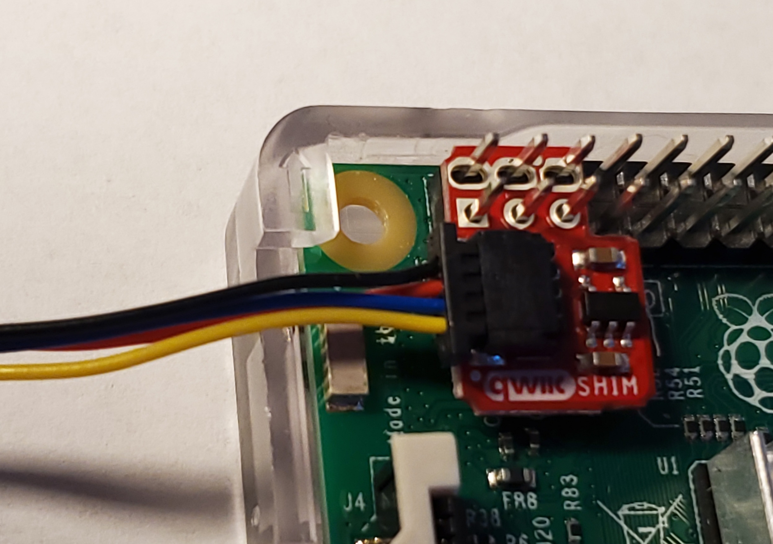
Fig. 60 Installing a SHIM on a Raspberry Pi#
Then use a Qwiic cable to connect from the SHIM to the AHT20 temperature sensor (see Fig. 61).

Fig. 61 Connecting the AHT20 Temperature Sensor#
Next, plug the sensor into the OLED display (see Fig. 62).

Fig. 62 Connecting the OLED Display#
After you reboot, enter the command in Listing 29 to see what comes up:
sudo i2cdetect -y 1
     0  1  2  3  4  5  6  7  8  9  a  b  c  d  e  f
00:                         -- -- -- -- -- -- -- --
10: -- -- -- -- -- -- -- -- -- -- -- -- -- -- -- --
20: -- -- -- -- -- -- -- -- -- -- -- -- -- -- -- --
30: -- -- -- -- -- -- -- -- 38 -- -- -- -- 3d -- --
40: -- -- -- -- -- -- -- -- -- -- -- -- -- -- -- --
50: -- -- -- -- -- -- -- -- -- -- -- -- -- -- -- --
60: -- -- -- -- -- -- -- -- -- -- -- -- -- -- -- --
70: -- -- -- -- -- -- -- --
You should see two devices, with the hex addresses of 0x38 and 0x3d. If nothing comes up, recheck your connections.
With that working, let’s write some code that will display the current temperature and humidity, as shown in Listing 30.
 1"""
 2This prints the temp and humidity from the AHT20 sensor
 3available frokm Adafruit.
 4https://www.adafruit.com/product/4566
 5
 6Before you use this program, you'll need to install the
 7Adafruit library with:
 8pip3 install adafruit-circuitpython-ahtx0
 9"""
10import time
11import board
12import adafruit_ahtx0
13
14
15def setup_aht20():
16    # Create sensor object, communicating over the board's default I2C bus
17    # uses board.SCL and board.SDA
18    i2c = board.I2C()
19    sensor = adafruit_ahtx0.AHTx0(i2c)
20    return sensor
21
22
23def get_readings(sensor):
24        temp_c = sensor.temperature
25        temp_f = temp_c * (9.0 / 5.0) + 32.0
26        humidity = sensor.relative_humidity
27        return temp_f, humidity
28
29
30def run_display_loop(sensor):
31    while True:
32        try:
33            temp_f, humidity = get_readings(sensor)
34            print(f"Temp: {temp_f:4.1f} F, Humidity: {humidity:4.1f}%")
35        except OSError as error:
36            print(f"Error reading data: {error}")
37
38        time.sleep(2)
39
40
41def main():
42
43    try:
44        # Try to get the sensor
45        sensor = setup_aht20()
46    except ValueError as error:
47        # Error getting sensor
48        print(f"Error, unable to find the sensor.")
49        print(f"{error}")
50        print(f"Make sure it is plugged in and run 'sudo i2cdetect -y 1' to verify.")
51        return
52
53    run_display_loop(sensor)
54
55
56main()
First, we initialize and start I2C on the computer (line 18). Then, we open a connection to our temperature sensor (line 19). Next, we get our temperature and humidity sensor readings (line 33). If you are in the U.S., you might want to convert the default Celsius to Fahrenheit (line 25). The code loops and displays the sensor readings every two seconds.
Once that is working, write some code to try out the OLED display, as shown in Listing 31.
 1"""
 2Demo for Adafruit's OLED display:
 3https://www.adafruit.com/product/326
 4
 5Before running, install the library with:
 6pip3 install adafruit-circuitpython-ssd1306
 7"""
 8
 9import board
10import busio
11import digitalio
12from PIL import Image, ImageDraw, ImageFont
13import adafruit_ssd1306
14
15# You'll need to put the OLED screen's address here.
16# You can see current addresses with:
17# sudo i2cdetect -y 1
18OLED_DEVICE_ADDRESS = 0x3D
19
20# Change these to the right size for your display!
21OLED_WIDTH = 128
22OLED_HEIGHT = 64
23
24BORDER = 5
25
26
27def setup_oled():
28    # Set up i2c
29    i2c = board.I2C()
30
31    # Define the Reset Pin
32    oled_reset = digitalio.DigitalInOut(board.D4)
33
34    # Connect to device
35    oled = adafruit_ssd1306.SSD1306_I2C(OLED_WIDTH,
36                                        OLED_HEIGHT,
37                                        i2c,
38                                        addr=OLED_DEVICE_ADDRESS,
39                                        reset=oled_reset)
40
41    return oled
42
43
44def create_image(text):
45    # Create blank image for drawing.
46    # Make sure to create image with mode '1' for 1-bit color.
47    image_size = (OLED_WIDTH, OLED_HEIGHT)
48    image = Image.new("1", image_size)
49
50    # Get drawing object to draw on image.
51    draw = ImageDraw.Draw(image)
52
53    # Draw a white background
54    rect = (0, 0, OLED_WIDTH, OLED_HEIGHT)
55    draw.rectangle(rect, outline=255, fill=255)
56
57    # Draw a smaller inner rectangle
58    rect = (BORDER,
59            BORDER,
60            OLED_WIDTH - BORDER - 1,
61            OLED_HEIGHT - BORDER - 1)
62    draw.rectangle(rect, outline=0, fill=0)
63
64    # Load default font.
65    font = ImageFont.load_default()
66
67    # Draw Some Text
68    font_width, font_height = font.getsize(text)
69    position = (OLED_WIDTH // 2 - font_width // 2,
70                OLED_HEIGHT // 2 - font_height // 2)
71    draw.text(position, text, font=font, fill=255)
72
73    return image
74
75
76def main():
77    try:
78        oled = setup_oled()
79    except ValueError as error:
80        # Error getting sensor
81        print(f"Error, unable to find the OLED screen.")
82        print(f"{error}")
83        print(f"Make sure it is plugged in and run 'sudo i2cdetect -y 1' to verify.")
84        return
85
86    image = create_image("Hello World!")
87
88    # Display image
89    oled.image(image)
90    oled.show()
91
92main()
First, a function sets up I2C and opens a communications channel to the OLED display (lines 27-39). It returns a class that will manage commands to the display. Next, the create_image function (line 44) creates an image to display. It uses the Python Pillow library to create the image (line 48), clear it to white (lines 53-55), create a black inset rectangle (lines 57-62), and then draw the centered text (lines 64-71). Finally, we can take that image and display it (line 90).
With these two listings, see if you can write a program that will read in the temperature and humidity, then display it on the OLED screen. Example code is available at https://github.com/pvcraven/networking_down_under/blob/master/i2c_temp_oled.py.
Summary#
In this chapter you learned to run Wireshark to capture network packets. You learned how to get and change your Layer 2 MAC address. You sent raw Ethernet packets over the network, and then used iperf3 to test how fast you can send and receive data over a network connection. You also looked at scanning and connecting with Bluetooth. Finally, you used the I2C to read sensor data and output it via a small OLED display. You covered a lot of ground on how to pass data directly from one node to another. In the next two chapters, you’ll learn how to build on this with Layer 3 and route data across a network of nodes. With Layer 3 you’ll no longer be limited to just point-to-point communications.